

 The J1939 network is critical for communication between the various electronic control units (ECUs) in a semi-truck, such as the engine, transmission, ABS, and body control modules. When issues arise, they can lead to system malfunctions or complete communication failures. Here are the most common J1939 issues on semi-trucks.
1. J1939 Network Physical Layer Problems
The physical wiring and connectors of the J1939 network are susceptible to wear and damage due to the harsh operating conditions of semi-trucks.
Common Issues
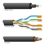
- Damaged Wires: Twisted pair (CAN High and CAN Low) wires can get pinched, cut, or chafed.
- Corroded Connectors: Moisture and road salts can corrode diagnostic or ECU connectors.
- Loose Connections: Vibrations from driving can loosen connectors, causing intermittent communication.
- Short Circuits: Shorts between CAN High and CAN Low or to ground/power can disrupt communication.
2. Termination Resistor Failures
Termination resistors are critical for maintaining the integrity of the CAN signal.
Common Issues
- Missing Resistors: A missing termination resistor can cause an open circuit and disrupt communication.
- Failed Resistors: A resistor may lose its specified 120-ohm value, leading to improper signal termination.
3. Network Topology Errors
J1939 requires a proper network layout with a daisy-chained structure and no excessive branching.
Common Issues
- Improper Splicing: Additional devices added incorrectly to the network can create “stubs” that degrade signal quality.
- Too Many Nodes: Exceeding the maximum allowable number of nodes (ECUs) on the network can cause data collisions.
- Incorrect Placement of Termination Resistors: Resistors placed incorrectly within the network can cause communication issues.
4. Electrical Interference
The J1939 network operates in an environment filled with electrical noise from other systems on the truck.
Common Issues
- Electromagnetic Interference (EMI): Poorly shielded wires can pick up noise from alternators, inverters, or other electronic systems.
- Voltage Spikes: Sudden electrical surges, such as jump-starting, can damage ECUs or disrupt communication.
5. Faulty ECUs
A malfunctioning ECU can disrupt the entire J1939 network.
Common Issues
- Hardware Failures: Internal component failures in an ECU can prevent it from sending or receiving messages.
- Software Glitches: Outdated or corrupted firmware can cause communication errors.
- Incorrect Configuration: Misconfigured ECUs can send incorrect or excessive data, leading to bus overloads.
6. High Bus Load
If too much data is transmitted on the J1939 network, it can overwhelm the system.
Common Issues
- Excessive Messages: One or more ECUs sending unnecessary or repeated messages (bus flooding).
- Slow ECUs: Older ECUs may not process data fast enough, causing delays in communication.
7. Grounding
Improper grounding can lead to unstable communication or ECU damage.
Common Issues
- Poor ECU Grounding: Faulty or loose ground connections for an ECU can cause intermittent communication issues.
- Ground Loops: Multiple ground paths can introduce electrical noise into the network.
8. Diagnostic Port
The diagnostic port is the primary access point for J1939 troubleshooting, and issues here can complicate diagnostics.
Common Issues
- Broken or Bent Pins: Damaged pins in the diagnostic port can interrupt data access.
- Incorrect Wiring: Incorrectly wired diagnostic ports can prevent tools from reading the network.
9. Environmental Factors
The harsh environment that trucks operate in can exacerbate issues.
Common Issues
- Extreme Temperatures: Heat can degrade insulation, and cold can cause brittle wires.
- Moisture Ingress: Water can cause corrosion or short circuits in connectors.
- Vibration and Shock: Constant movement can lead to physical wear on wiring and connectors.
10. Lack of Proper Maintenance
Neglecting regular inspection and maintenance can lead to preventable issues.
Common Issues
- Ignored Early Warnings: Small issues like intermittent faults are often ignored until they become major problems.
- Dirty Connectors: Dirt and debris can block proper electrical contact.
Summary of Key Problem Indicators
- Active Fault Codes: SPNs and FMIs indicating network or ECU issues.
- No Communication: Diagnostic tools cannot establish a connection.
- Intermittent Issues: Systems (e.g., ABS, engine) behaving erratically.
- Slow or No Response: Delays or failures in ECU communication.
Preventive Measures
- Regular Inspections: Check wiring, connectors, and resistors for damage or wear.
- Use Dielectric Grease: Prevents moisture ingress in connectors.
- Follow OEM Guidelines: Ensure network topology adheres to manufacturer specifications.
- Shielding and Routing: Properly shield wires and route them away from high-EMI areas.
By addressing these common issues promptly and performing regular maintenance, semi-truck owners can reduce downtime and costly repairs related to J1939 network failures.
What Is The J1939 Network Made Of?
 J1939 components are primarily part of the CAN (Controller Area Network) system, which includes physical wires, connectors, and electronic components. Here’s a breakdown of the materials typically used:
1. J1939 Network Physical Layer Materials
The physical layer of the J1939 network consists of the twisted pair wiring, connectors, and resistors:
Wires (CAN High and CAN Low)
- Conductors: Typically copper or tinned copper for excellent conductivity and corrosion resistance.
- Insulation: Usually made of polyethylene (PE), polyvinyl chloride (PVC), or cross-linked polyethylene (XLPE) for durability, flexibility, and resistance to heat and chemicals.
- Shielding: May include aluminum foil or braided copper shielding to prevent electromagnetic interference (EMI).
Connectors (Diagnostic Port and ECU Connections)
- Contacts: Gold-plated copper alloy or nickel-plated brass for reliable electrical connection and corrosion resistance.
- Housing: Thermoplastics such as nylon or polycarbonate for durability, heat resistance, and protection against moisture.
Termination Resistors Material
- Resistor Core: Made of materials like ceramic or metal oxide for stability and precision.
- Leads: Typically tinned copper for solderability and corrosion resistance.
- Encapsulation: Epoxy resin for protection against heat, moisture, and vibration.
2. Electronic Components in ECUs Materials
- Circuit Boards: Made of fiberglass-reinforced epoxy laminate (FR4) for strength and electrical insulation.
- Chips and ICs: Composed of silicon and enclosed in ceramic or plastic packages.
- Capacitors, Resistors, and Inductors: Use combinations of ceramic, metal, and polymer materials.
3. Protective Materials
- Cable Sheaths: Often made of PVC, thermoplastic elastomer (TPE), or rubber to protect the internal wires from abrasion, oil, and environmental exposure.
- Grommets and Seals: Made of silicone rubber or EPDM (ethylene propylene diene monomer) for environmental sealing and vibration dampening.
4. Shielding Materials
- Foil Shielding: Made of aluminum or copper for EMI protection.
- Braided Shielding: Composed of tinned copper or bare copper for flexibility and durability.
Why These J1939 Network Materials Matter
The Choice of J1939 Network Materials Ensures
- Electrical Performance: Copper provides low resistance and high conductivity for signal integrity.
- Durability: Insulation and sheathing materials protect against harsh trucking environments (heat, cold, oil, chemicals, and vibration).
- Reliability: Plated contacts and sealed connectors prevent corrosion and ensure long-term performance.
By understanding these materials, you can better evaluate the quality of replacement parts and cables used in your J1939 network. High-quality components often lead to fewer failures and lower long-term costs.